BuildingZone
Symbol | 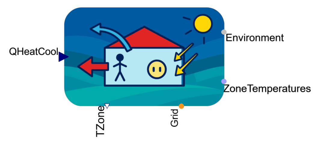 |
|---|
Use
The Building Zone component simulates various influences on the indoor air temperature. It additionally includes and considers the behavior of persons inside the building which have effect on the electricity and heat demand of the energy system. it provides a flexible Modelica-based interface for both heating and cooling energy input.
Parameters and Connectors
The Building Zone requires a lot of different parameters from different domains as it is very complex model describing a lot of influencing characteristics on buildings' heat demand (c.g. Model Background).
Therefore, there are at least 25 parameter dialogs describing different categories of parameters:
Model Setup
Zone Size, Occupation and Ventilation System
Construction Parts
Model Setup
A zone model can become a part of a multi-zone building model using the ▶ZoneTemperatures interface (c.f. Temperature Distribution. This enables the modeling of complex buildings with different rooms or zones and different heat and electricity demand. The ▶ZoneTemperatures interface becomes available if NumberZones (in parameter dialog Model Initialization) is higher than '1' and at least one of parameters contactBoundX (in one of the parameter dialogs Boundary X - I) is higher than '0'.
Building Zone cannot simulate the behavior of heating surfaces (e.g. floor heating). To model the heat input via those components, the user needs to add a suitable Green City (e.g. Heating System) or MSL (e.g. RealExpression) element which provides an adequate heat power output signal to the ▶QHeatCool connector. This connector is only available if the parameter LoadCalculation (in parameter dialog Model Initialization) is 'false'. This option allows the user a more flexible way to connect the desired energy system model which now can also be ventilation system providing heated air or even a cooling system which provides cooling power during summer (i.e. ▶QHeatCool must become negative though).
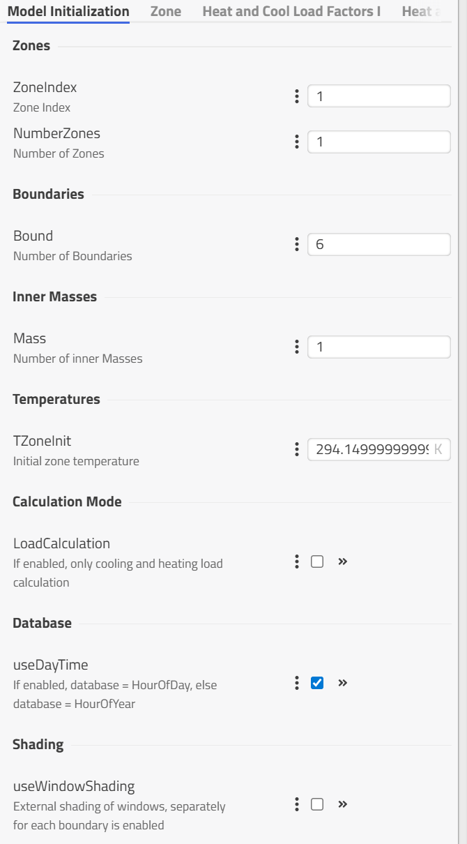
The basic parameters of the Building Zone are available in Model Initialization dialog. These parameters define the basic model configuration incl. available inputs and outputs as well as the actual model size.
NumberZones: Total number of zones in a multi-zone model, if this zone is connected to other neighboring zones
ZoneIndex: Zone ID in a multi-zone model
Bound: Number of boundaries (max: 9, min: 1), like walls, ceilings, floors, etc.
Mass: Number of inner masses (max: 4, min: 0), like inner walls, furniture or other relevant inner masses
TZoneInit: Indoor air temperature during initialization
LoadCalculation: 'true' means calculation of heating and cooling loads with reference indoor air temperature, 'false' generates a dynamic model setup which simulates the indoor air temperature based on heat gains and losses as well as heat supply and available capacities.
useDayTime: Configures the time format of input data sets (e.g. persons' behavior and electricity demand) - 'true': 0..24h, 'false': 0..8760h
useWindowShading: Enables controlled shading of windows in each boundary (e.g. via blinds)
Several configuration options cause different setups of available input connectors. If LoadCalculation is set to 'false', ▶TZoneRef occurs. It is now mandatory to connect a suitable input (e.g. Modelica-RealExpression) to this connector which defines the reference indoor air temperature.
If window shading is enabled, the connector ▶WindowShading becomes available which describes a controlled individual shading signal for each boundary. However, this signal (i.e. 0: fully irradiated, 1: fully shaded) only comes into effect if the corresponding boundary (i.e. boundary index corresponds to vector index) includes a window. Again use a suitable input like a Modelica-RealExpression (vector) to define this additional energy management characteristic.
Zone Size, Occupation and Ventilation System
The second category of parameters considers a wide range of building parameters including different types of zone occupation description as well as general zone characteristics without links to construction parts.
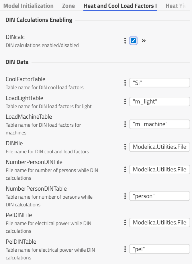
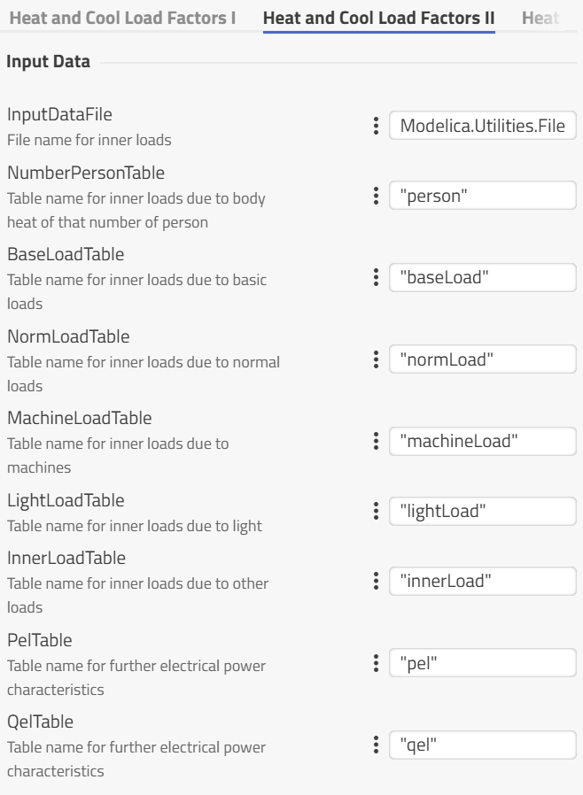
The zone occupation depends on the selected type of input data sets. The parameter DINcalc (in the parameter dialog Heat and Cool Factors I) defines if the input data sets of internal heat loads, electrical power demand and the presence of persons will use DIN standards (DIN 2078) or individual user-specific data.
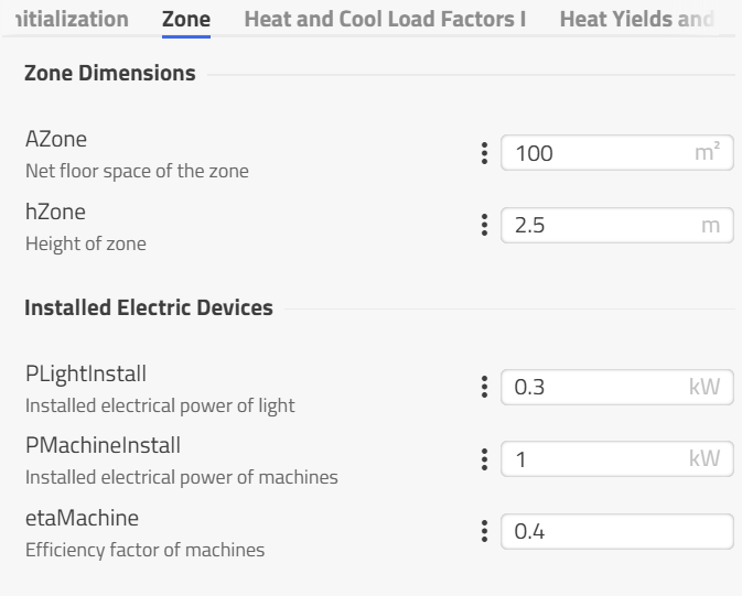
The parameter dialog Zone describes some more general zone parameters incl. a DIN standard based description of installed electric devices (i.e. only available if DINcalc = 'true'):
PLightInstall: Installed electric power of lighting
PMachineInstall: Installed electric power of machinery
etaMachine: Efficiency factor of installed electric machinery
Furthermore, the model considers internal heat yields per person (standard DIN values set as default values):
QBody: Body heat per person
QPersonColdWater: Heat losses due to cold water use per person
QPersonElectricity: Heat yields depending on the use of electric devices
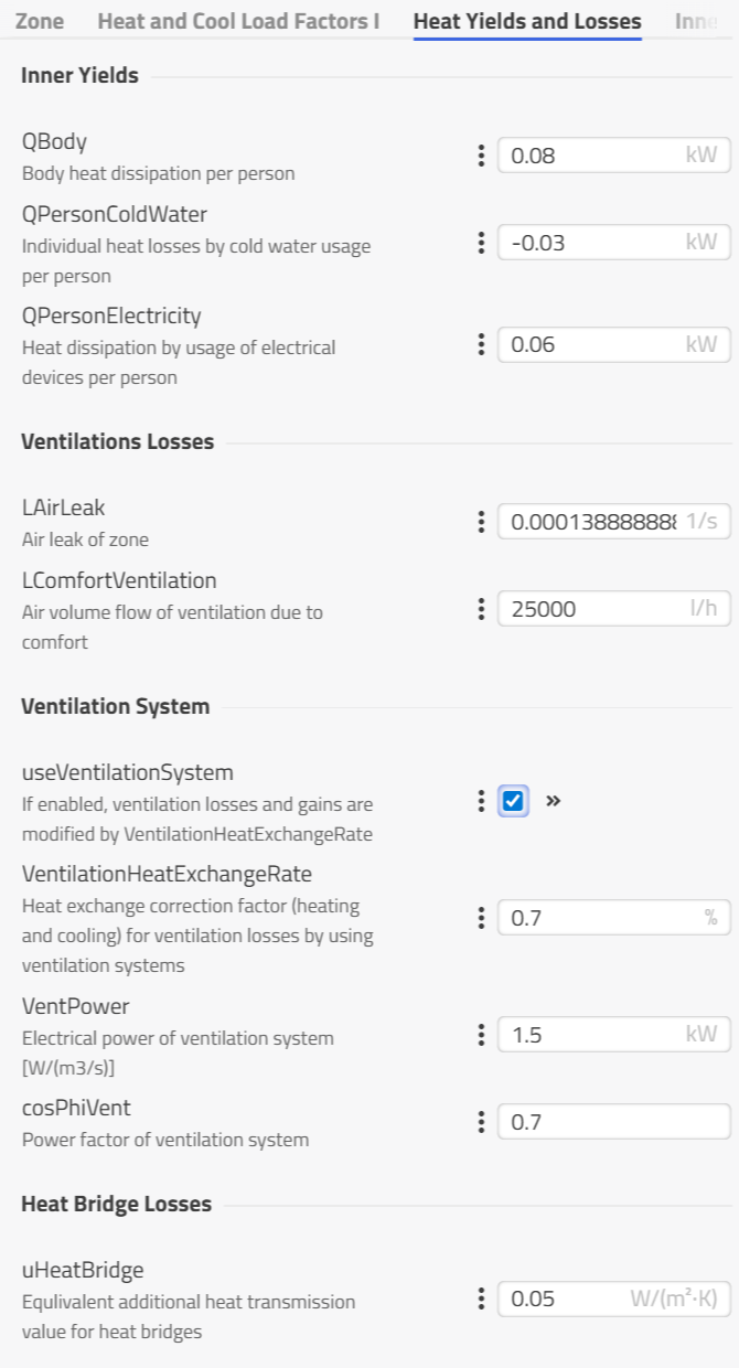
The ventilation losses are defined via the air leakage (LAirLeak) through boundaries. To assure an acceptable CO2-level and an adequate humidity, in the zone, further ventilation is needed. This causes an additional air flow between the inside and outside of the zone (LComfortVentilation, i.e. typically arount '25 m3/h' per person). This air flow results from window openings or mechanical ventilation (i.e. available if useVentilationSystem is 'true'). A mechanical ventilation system causes additional electricity demand depending on the resulting air flow (VentPower, in average around '1,500 W' per m3/s air flow). VentilationHeatExchangeRate and cosPhiVent describe additional technical parameters of the ventilation system.
Construction Parts
Construction parts can be both Inner Masses and Boundaries. Inner masses only represent additional heat capacities of the zone. Boundaries describe both heat capacity and heat losses through the zone's building envelope.
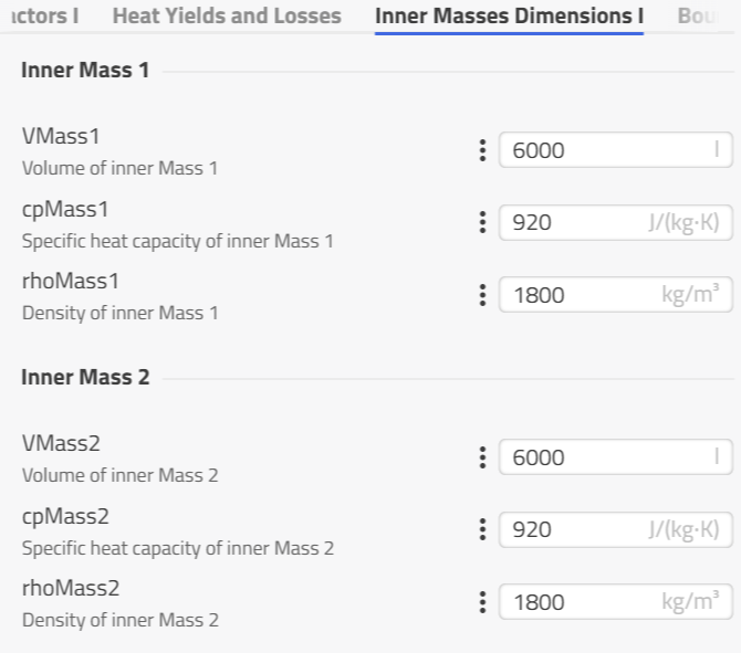
To simplify the simulation process, the inner masses temperature always remains on the indoor air temperature level. Each inner mass (max. 4, min. 0) is described by the following three parameters:
VMass: Volume
cpMass: Specific heat capacity
rhoMass: Density
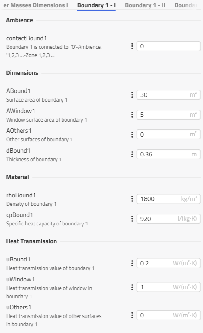
If a building consists of several building zones, besides heat losses to the outside, additional heat is exchanged between different zones. Therefore, it is necessary to connect neighboring zones within the simulation model. This requires the maximum number of zones to be higher than '1'. Furthermore, the parameter contactBound defines ID of the neighboring zone of each construction part (1, 2, 3 ....). If it is '0', the construction part is an outer element.
The parameterization of construction parts of the building zone's envelope is much more complex. Each part has to be parameterized separately. On the one hand, this includes construction part specific surface areas (e.g. walls, windows etc.) and thicknesses:
ABound: General construction part surface area (incl. AWindow & AOthers)
AWindow: Surface area of windows inside the construction part
AOther: Surface area of other components, like doors, inside the construction part
dBound: General thickness of the construction part
Besides geometric parameters, zone boundaries require additional material and heat transmission parameters (i.e. U-Values):
uBound: U-Value of general construction part
uWindow: U-Value of window inside the construction part
uOthers: U-Value of of other components inside the construction part
rhoBound: General density of the construction part
cpBound: General specific heat capacity of the construction part
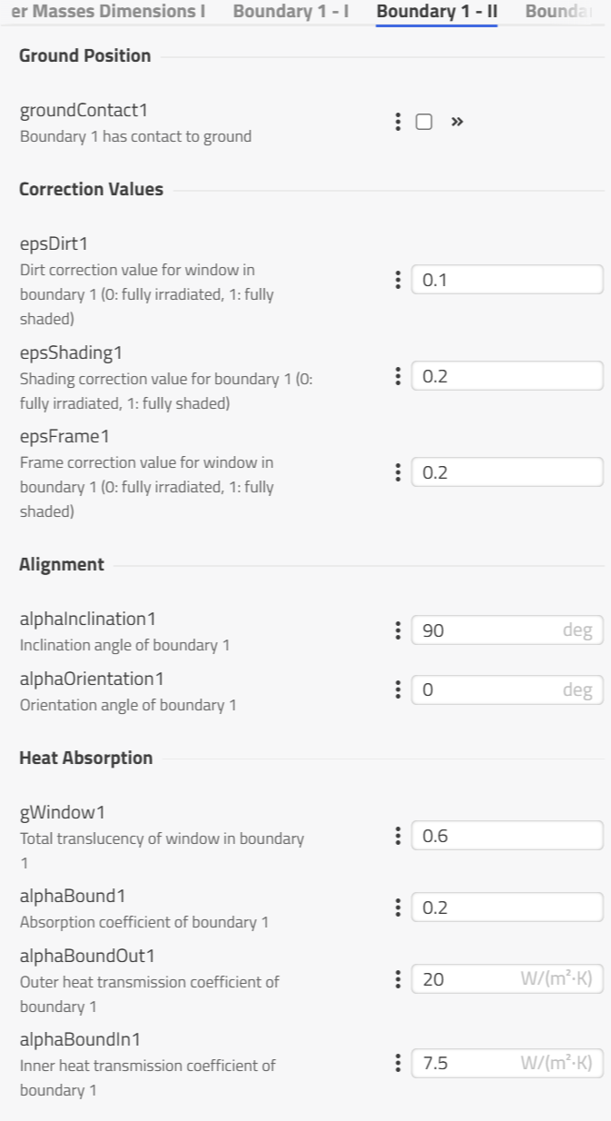
To configure the zones, the alignment of each boundary side must be determined via inclination and orientation angle:
Inclination angle (alphaInclination): 90° vertical wall, 0° flat ceiling or floor
Orientation angle (alphaOrientation): 0° - boundary normal points towards north, 90° - east, 180° - south, 270° west
Additional correction factors (epsDirt, epsShading, epsFrame) allow for a more detailed description of the solar irradiation absorption. Note that the frame (epsFrame) and dirt (epsDirt) correction factors are only used to reduce solar irradiation absorption through the windows.
The shading (epsShading) correction factor is additionally used to reduce the heat absorption of the opaque construction part as well. Note that internal building construction parts (i.e. internal walls or ceilings) are not irradiated by the sun and thus the corresponding shading correction factor must be '1'. Generally, these correction factors reduce solar yields (i.e. maximum shading: '1').
If a boundary is adjacent to soil, the parameter groundContact must be set to 'true' and the average depth (depthBound) of soil need to be defined. For vertical walls with soil contact, use the average depth of the wall. In these cases, the main heat transmission takes place via heat conductance. Therefore, the outer heat transmission factor (alphaBoundOut) won't be available anymore.
In any other case, when it's available, alphaBoundOut is around '20 W/m2' for external construction parts and around '7.5 W/m2' for internal construction parts. The inner heat transmission factor (alphaBoundIn) typically gets values between '6.5 W/m2' and '9.5 W/m2' depending on type and alignment of the construction part. The additional absorption coefficient (alphaBound) describes the influence of the external construction part color on solar heat absorbency (white '0.2', dark grey '0.8'). Furthermore, the heat absorption through windows is limited by the glass-specific total translucency value gWindow (i.e. 0.6 to 0.75 for simple glazing, <0.2 for thermal insulation glazing).
The Results dialog provides some most relevant output characteristics of the model. However, there are a lot of more internal simulation results available, such as solar gains, ventilation losses, etc. These results can be enabled via the TypeDesigner by setting corresponding and predefined output variables from protected to public.
Model Background
The zone temperature depends on various influences:
Heat transmission through walls, windows and other boundaries (e.g. doors) (qtrans)
Heat bridge losses (qHB)
Solar yields (qsol)
Ventilation losses (qvent)
Internal yields and losses via persons as well as electricity and water usage (qel, qpers)
Internal heat storage (air, walls, inner masses) (Q)
Heating and cooling via external heat or cooling energy input (qHT)
