DCGrid
Symbol |  |
|---|
Use
The grid component sums the overall power demand of the connected (maximum of 6) components.
The Grid covers the following applications:
Basic: Normal grid connection for the different components
Sub Grid For Sum Calculation: Activate a new connector to let the current grid (sub grid) connect to a main grid (sum of different grids and components)
Grid For Inverter: Connect the current dc grid via a grid inverter to a low voltage ac grid
Parameters and Connectors
Basic
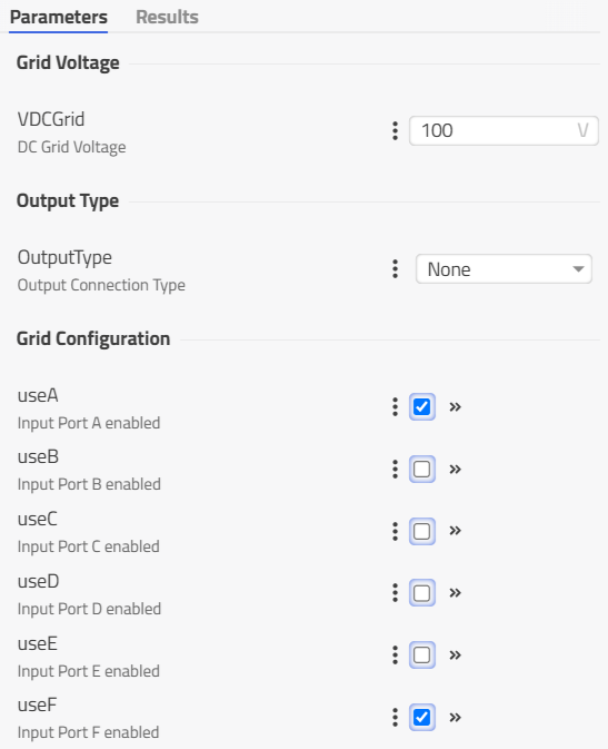
The grid in the basic configuration (OutputType is None) has up to 6 connectors ▶GridA to ▶GridF, which can be activated using the parameters useA to useF. With the grid voltage parameter VDCGrid, the dc grid voltage can be adjusted. Using the current transmitted by each connector ( ▶GridA to ▶GridF), the grid model calculates the actual power demand of each connected device and overall power demand.
If the overall power P is positive the power demand is summed and an electrical energy demand determined ESupply. If negative, the resulting power P is summed and used to define the electrical energy fed into the grid EFeed.
Sub Grid For Sum Calculation
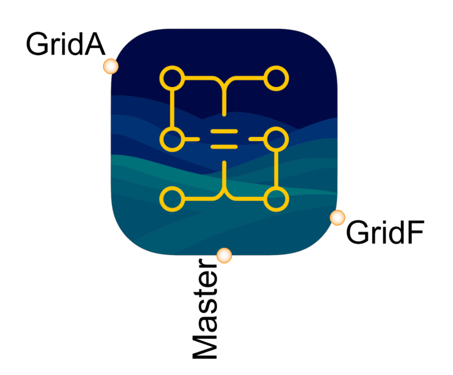
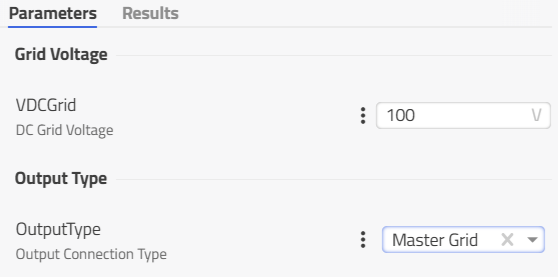
When the parameter OutputType is set to Master Grid the connector ▶Master is visible and allows to connect the current sub grid to another master grid (normal connector ▶GridA to ▶GridF) that other master grid will then sum up all the individual grid components together.
Grid For Inverter
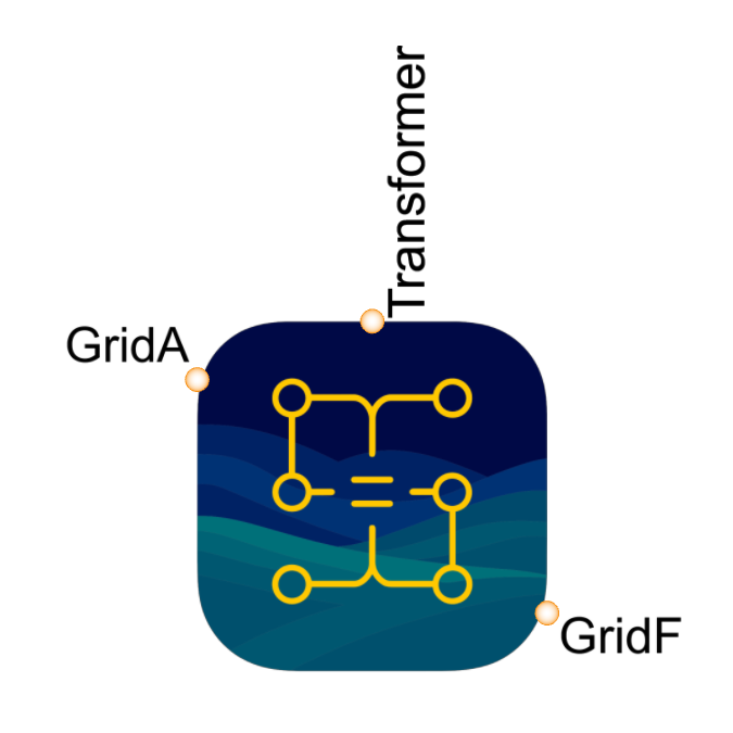
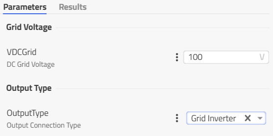
When the parameter OutputType is set to Grid Inverter the connector ▶Transformer is visible and allows to connect the Grid to another Grid with different VDCGrid via a grid inverter model.